Background:
The Finite Element Method (FEM) is the main numerical method implemented in most commercial CAE software packages, e.g. NASTRAN, ANSYS, ABAQUS, etc. Although great efforts and intensive research on the FEM have been made during the past several decades, the problems associating with the intrinsic drawbacks of the FEM are still kept unresolved. The problems lie in the following aspects:
- The CAE model (approximate grid model) is completely different from the CAD model (continuous parametric model), not only in geometry and topology, but also in representation data structure. This makes the interaction between CAE and CAD extremely difficult. A truly seamless interaction is determinatively impossible.
- The task of proper meshing of an engineering structure for any FEM analysis is always challenging and keeps the most critical part of the analysis. The accuracy of the FEM is severely dependent on the quality of the mesh. Due to obvious restriction of element connectivity and requirements of appropriate values of their aspect ratios, in many cases the high quality elements is difficult and cumbersome to obtain. A completely automatic meshing for arbitrary structures tool is still unavailable.
- Many kinds of abstract element, e.g. beam element, shell element, bar element, spring element, etc., are used in the FEM (usually up to hundreds of elements included in a mature commercial FEM software package). These elements are all based on some mathematic assumptions. Selection of proper element type and reasonable explanation to the computational results require sound theoretical background, good knowledge of all elements performance and rich experience in numerical analysis. This limits its users to specialized experts, only.
- The FEM is based on the equivalent weak form of the governing equation and the boundary conditions of the BVP. The trial functions in the FEM formulation must be at least C1 continuous. The C1 continuity requirement for the trial function increases the difficulty of constructing the elements, especially shell and beam elements, and leads to a number of contradictions, e.g. the contradiction between conforming and non-conforming elements, accurate integration and locking problems, reduced integration and hourglass modes, accuracy and stability in penal function method, etc.
- Theoretically, the weak form underlying the FEM means that the FEM is always inaccurate, as the governing equation is not exactly satisfied but satisfied in an average sense. It is just guaranteed that an FEM solution converges when the element size approaching zero. Therefore, errors of the FEM come from not only the approximation of the trial function but also from the “weak form” theory. Meanwhile, for a stress analysis by FEM, as stresses are calculated from the derivatives of displacements, the accuracy for stresses is lower by one order than displacements. In many cases, however, the structure design engineerers are more concerned by the stress values.
- In FEM analyses, the geometric model of the analyzing structure is often modified and simplified due to connectivity and aspect ratio of elements and to make the model meshable by some meshing tools. In the modification, small sized features at the connecting area between different parts of the structure, such as the fillets, welding seams, etc. are simply omitted. These features, however, are most possibly the places where local stress concentrations take place and cracks originate from. Moreover, further assumptions are required to connect different kinds of elements in the assembled matrix, e.g. connection between solid and shell elements. This leads to much worse accuracy for the stresses or even wrong results, and thus makes the entire analysis unbelievable and useless.
To overcome the above problems, we have put forward the concept of Complete Solid Stress Analysis (CSSA) and proposed the Boundary Face Method (BFM) based on the Boundary Integral Equation (BIE) to carry out the CSSA. The BFM requires only boundary mesh, which can be obtained by discretizing each piecewise continuous panel of the body’s surface without restriction of element connectivity, hence, considerably simplifies the discretization task. Moreover, it uses the parametric representation of domain surfaces, only. Such representation is used in any CAD software and can be accessed in commercial packages via Open Architecture features (usually the in-process COM servers/objects can be exploited). This may considerably simplify the data pre-processing and lead to substantial resources savings.
The BFM has the following advantages:
- Potential to make direct use of a body’s parametric representation through Brep data structure of CAD packages. A CAE analysis can be set up directly on the CAD model, making automatic simulation possible.
- Use of abstract elements (e.g. shell, beam elements) avoided and no geometric simplification and data format conversion needed. Structures of any shape (bulky, thin or slender) and any part of the structure (e.g. fillet, weld seam, groove and small hole, etc.) are considered as three dimensional solids with their actual geometric sizes, making automatic meshing possible.
- Able to capture local stress concentration at arbitrary points on the structure. The accuracy for stresses results is of the same order with that for displacements. This merit is inherited from the BIEM.
- Convenient and natural way to solve problems involving infinite domains, e.g. noise, earthquake, electromagnetic wave, etc.
- Convenient and natural way to solve problems involving singularities, e.g. fracture, fatigue, crack propagation, etc.
Preliminary Achievements:
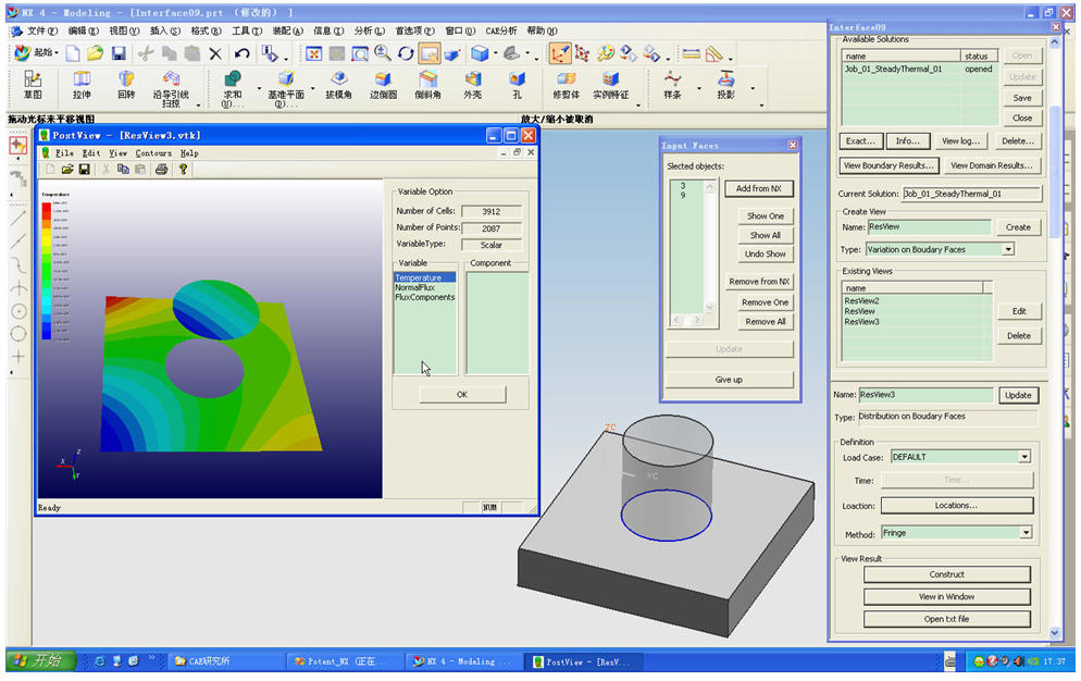
A primary version of CSSA software (Potent 1.0) has been developed. This software is completely integrated into the environment of the well known CAD package UG-NX. So far, the Potent 1.0 is able to solve problems in theories of static elasticity, steady state and transient heat transfer and acoustics.
The Potent 1.0 is not only more accurate and efficient than most well known commercial CAE packages (e.g. NASTRAN, ANSYS, etc.), but also exhibits the following extraordinary merits:
- Analysis can be easily performed by clicking some buttons in the UI of the NX-UG. It is not necessary for the users to master the knowledge about computational mechanics but just knowledge about material mechanics. With correctly imposed boundary conditions, accurate results can be obtained.
- Imposition of constraints and loads is also accomplished in the UI of the NX-UG. They are intuitively imposed on the CAD model rather than on the grid model. The mesh for the structure is automatically generated and invisible to the user. Therefore, the user does not need to care about meshing.
- Accurate prediction of stresses at arbitrary points can be made on a complex structure, e.g. on the welding seams of a welded frame structure. Case studies investigating how the welding style affects the structural strength can also be easily performed. As the analysis is conducted exactly on the same CAD model and also operated in the UI of the same CAD software, the structure can be modified quickly according to the computational results, and restart the analysis immediately. This process can be automatically repeated until an optimal design is achieved.
Typical Examples:
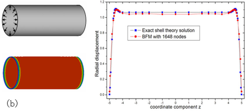
(1) Thin-shell like structures
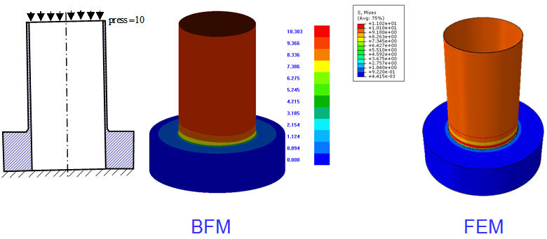
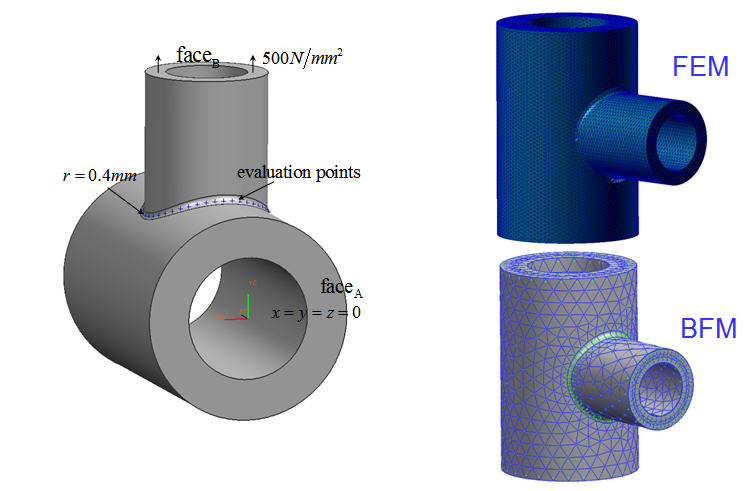
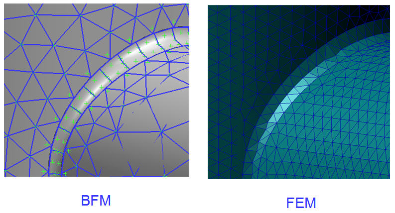
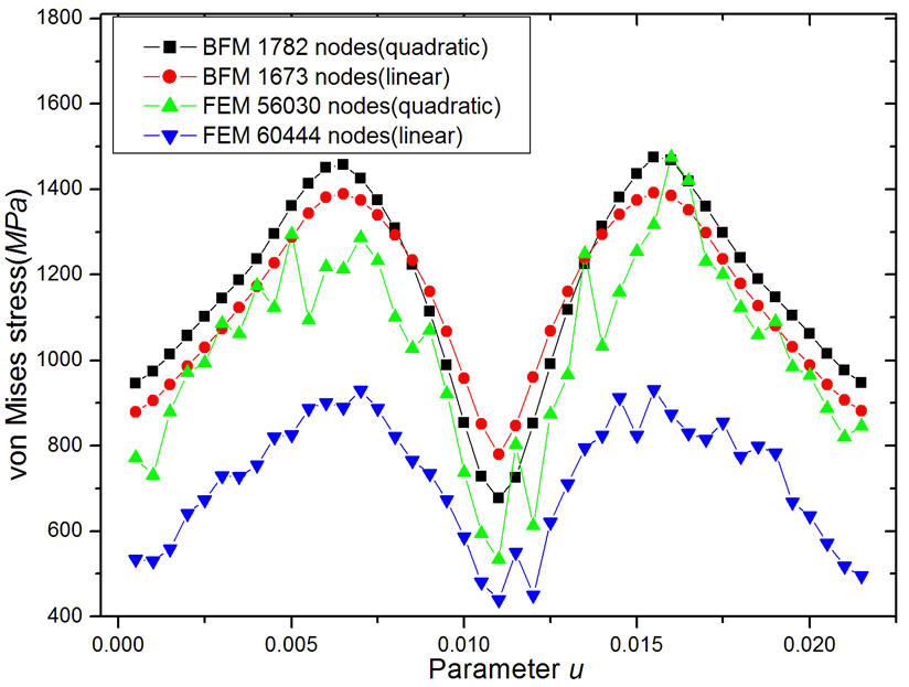
(2) Structures with small sized fillets
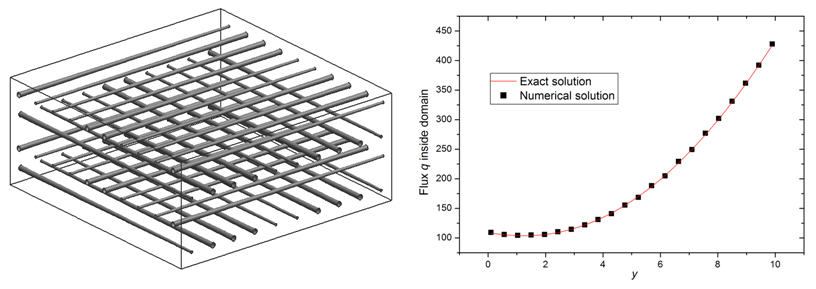
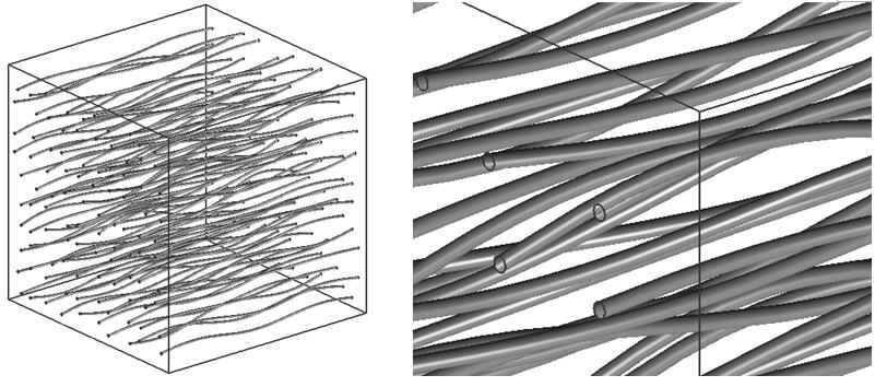
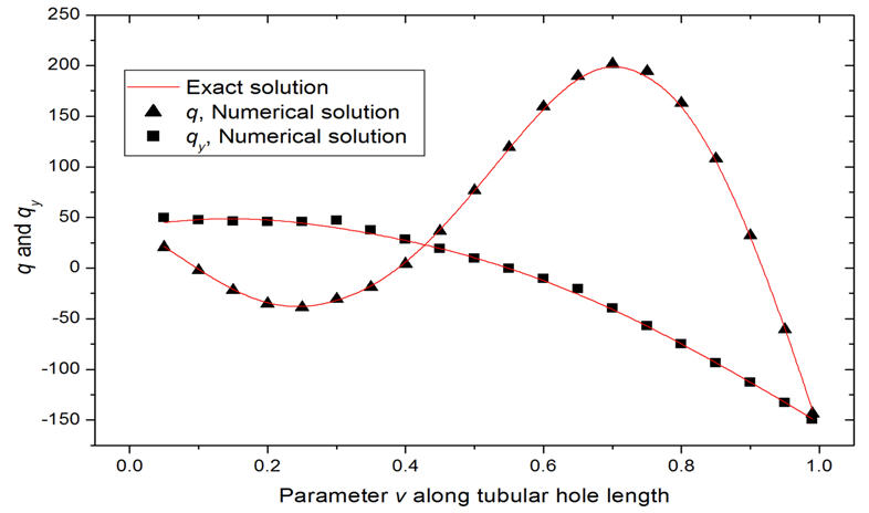
(3)Structures with slender pipes embedded (such as the cooling water pipes in engines)
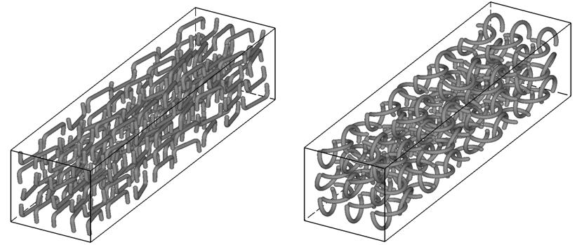
(4)CNT-reinforced Composites
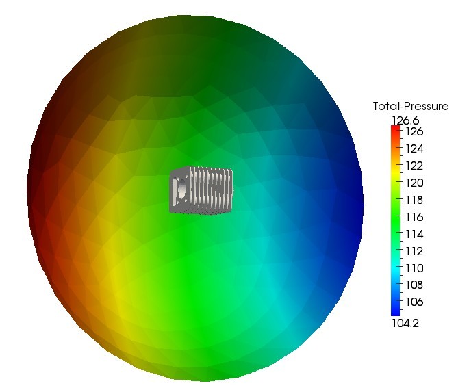
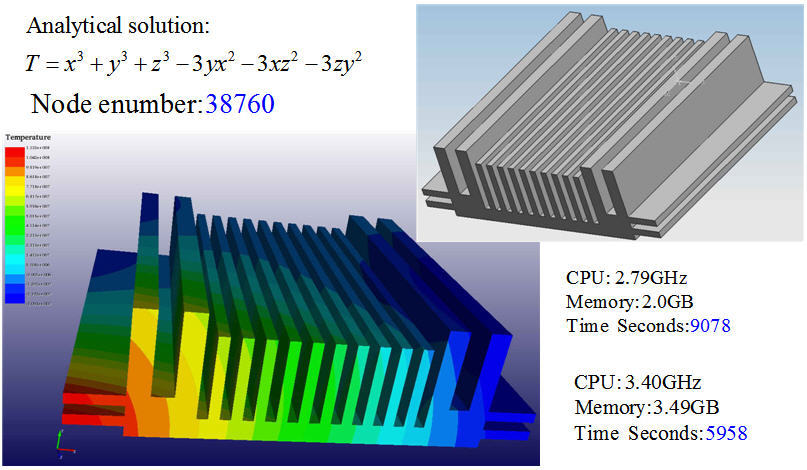
(5) Heat sink
Research Highlights in progress:
(1) Welding Seams Modeling in Frame Structures and Stress Analysis

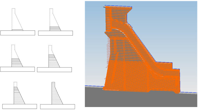
(2)Thermo-stress analysis during the construction process of gravity dam
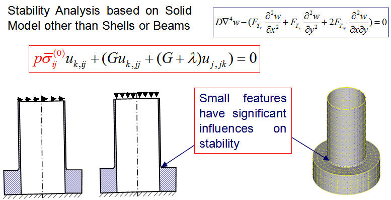
(3) CSSA for Structural Stability
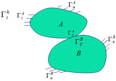
(4) Contact problem
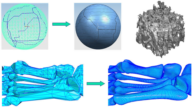
(5)Surface Reconstruction and Multi-Scale Stress Analysis for Bones
(6) Crack and Fatigue Analysis
(7) Structure vibration and acoustic problem